
Call us 9:00am - 6:00pm
953-700-0873
E-mail us
info@mechanismengineering.com
High Density Cleaners
This cleaner is designed to remove any staples, clips, and other debris from stock & keeping the consistency of 2 to 3 % in doing so, it protects the rotating parts of refiners, deflakes and other downstream equipments against excessive wear and breakage. Range: 500 LPM, 1000 LPM, 2000 LPM, 2500 LPM, 3000 LPM, 4000 LPM.
Principle :
Stock is fed tangentially into the inlet portion which along with centrifugal action of specially designed rotor is forced downward. The heavier impurities such as glass, pins, sand particles settles down in separate dirt vessel provided with two numbers of pneumatically operated pulp valves with auto control panel for auto purging. The reject time has to be adjusted according to the impurities present in the furnish and the time taken for filling the dirt vessel. Elutriation Water is fed into the two nozzles provided in the dirt vessel for minimizing fibre loss. The high density cleaner cleans pulp, fibres and all kind of stock suspension at consistencies up to 4%.
Features :
- Operating consistency 3 – 4%.
- Eliminates smaller heavy as well as bulky impurities such as glass particles, sand, pins, etc and protects onward screens from plugging & damaging.
- The system is provided with two nos. of Pneumatic operated reject valves with auto control panel.
- The equipment is complete with inlet nozzle, transparent zone and bottom junk trap.
- Efficient removal of impurities like sand, glass, clips, pins etc.
- Easy visual inspection of vortex through illuminated sight glass.
- Simple installation.
- Protection of further screening and refining equipment from wear and abrasion.
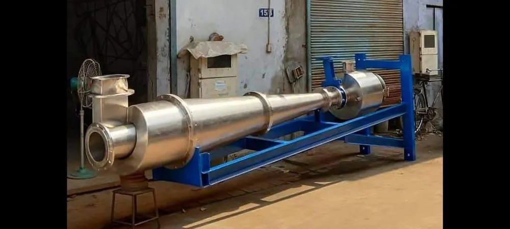
Technical Specifications :
The High Density Cleaner consists of one top part fabricated from S.S. 304 plate. A tangential inlet nozzle and one vertical outlet nozzle is provided on this. The nozzles are provided with secondary loose flanges for easy installation. One S.S. cone is attached to the top portion. Between this, one conical transparent glass is provided for viewing and controlling of the separation of rejected from the pulp. This glass is fitted in a MS chamber. This chamber is provided with a tube light at the rear side which enables the clear vision of separation. At the bottom, one S.S. reject collecting chamber is provided for the collection of rejected materials. This reject chamber is provided with a quick operating bottom door for draining of the rejects. This reject chamber is also provided with viewing glass which enables to see the quantity of reject collected. In between the separation zone and reject chamber when the cleaning of reject chamber is done. The reject chamber is provided with one tangential water inlet to control the separation of particles from the pulp and one outlet for releasing the air at the time of starting of the equipment. The whole assembly is fitted to a MS fabricated stand for installation process.